|
|
|
|
|
|
Idea
purpose, advantages, inventor
|
|
|
|
|
Research
comminution, material throughput, pressure distribution, modelling
|
|
|
|
|
Praxis
plant configuration, roller wear, references
|
|
|
|
|
|
|
|
Other Links
links to suppliers, universities and other institutions
|
|
|
|
|
Contact
for any questions please contact us
|
|
|
|
|
|
|
|
|
|
|
|
|
Results of the Throughput Tests
|
|
|
|
The results of the throughput tests are plotted in the form n = n(z). It can be
seen that all characteristic throughput curves in this graphic rendition can be approximated by the equation mentioned in the chapter phenomenons, see equation 11.
The throughput numbers n0 and throuput elasticities k of all tests are shown on the page elasticity.
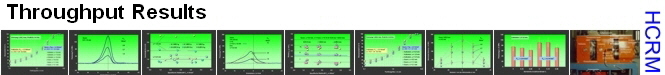
a) Influence of material and graining with smooth rollers
In the following diagram the n-z-straights for equal grainings of quartz and limestone with smooth rollers are shown (0.25/1.0mm, 1.6/6.3 mm, 0.1/6.3 mm). The results for quartz
can be approximated by only one straight line.For limestone a small graining effect can be seen. Nevertheless also for these results one straight line is educible in a first approximation.
The throughput of limestone with a n0 = 2.05*10-2 is approximately 70 % bigger than the throughput of quartz whereas the throughput elasticity of quartz with k = 730 is bigger than the elasticity of limestone with k = 440.
The high throughput of limestone is mainly caused by the formation of a material undercoating on the roller surface. The
result of this undercoating is - as explained before - that the drawing-in of the material is determined by the internal friction which is significantly higher than the external friction. The ratio of
internal and external friction angles measured in a ring sheer cell is approximately je/jx = 1.75, see friction angles of quartz and limestone.
|
|
|
 |
|
|
|
|
Comminution
grinding results for different materials
Exper. Setup
lab-scale mill, techn. data mill, intrumentation, feed materials, testing program, roller surface data, test execution
Throughput
literature, decoupling of throughput and comminution, energy absorption, characteristic
of different rollers, phenomenons, throughput results, elasticity, friction angle, specific throughput
Pressure Distribution
pressure diagrams
Press Tests
tests with a molding press
Modelling
mathematic model of the process
Signs and Symbols
nomenclature
|
|
|
|
|
|
|
|
Specific throughput of quartz and limestone, smooth rollers / Dissertation U. Lubjuhn, 1992 [25]
|
|
|
To proove the effect of the undercoating some tests with blank rollers were performed and the throughput during the first rotation was measured,
see specific throughputs.
In this case the increase of throughput compared to quartz is only 26 % for the graining 1,6/6,3 mm and 45 % for the graining 0,25/1,0 mm According to this the undercoating contributes 69 % respectively 42 % to the throughput increase. The smaller effect of the undercoating for the fine fraction could be explained by the fact that - looking at the maximum particle size - a material bed situation exists (s = 3,6 mm) whereas for the coarser graining almost direct contact exists (s = 4,9 mm). In the last-mentioned case only the friction between material and roller is decisive, for the material bed situation also the friction inside the material bed is important.
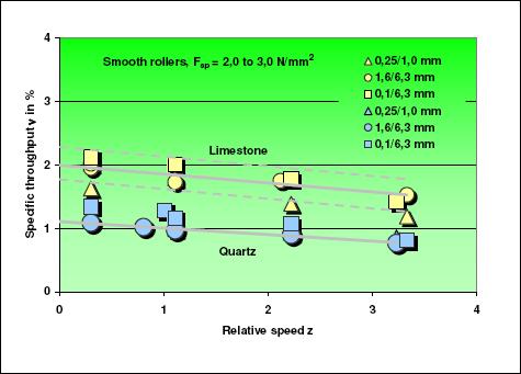
The width of the graining has an additional but minor effect. With smaller graining width the throughput decreases a little bit because the bulk
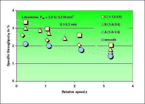
density is a little bit lower.It can be seen in the next diagram which shows the specific throuput for fractions with a graining width ratio of 1:1,3 and the best-fit lines taken from the previous diagram..
|
|
|
 |
|
|
Specific throughput of quartz and limestone, smooth rollers, coarse
narrow fractions / Dissertation U. Lubjuhn, 1992 [25]
|
|
|
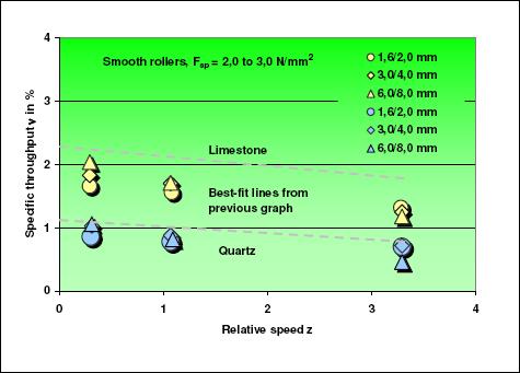
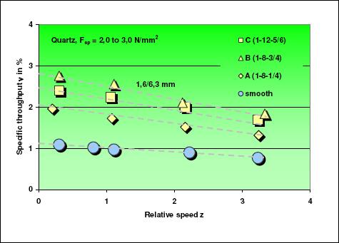
b) Influence of the profile
In the following six diagram all results of the throughput measurements are shown.The most significant findings are that (1.) the throughput with
corrugated rollers is up to 250 % higher than with smooth rollers, (2.) for corrugated rollers the material influence is substantially lower than for smooth rollers and (3.) a significant influence of the graining is visible.
The throughput numbers for limestone are generally higher than for quartz but decline a little bit sharper what means the throughput characteristic is less elastic.
|
|
|
 |
|
|
Specific throughput quartz 0,25/1,0 mm with different roller profiles / Dissertation Lubjuhn, 1992 [25]
|
|
|
 |
|
|
Specific throughput quartz 1,6/6,3 mm with different roller profiles / Dissertation Lubjuhn, 1992 [25]
|
|
|
 |
|
|
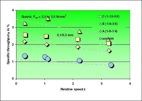
Specific throughput quartz 0,1/6,3 mm with different roller profiles / Dissertation Lubjuhn, 1992 [25]
|
|
|
 |
|
|
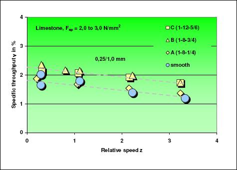
Specific throughput limestone 0,25/1,0 mm with different roller profiles / Dissert. Lubjuhn, 1992 [25]
|
|
|
 |
|
|
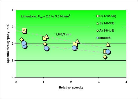
Specific throughput limestone 1,6/6,3 mm with different roller profiles / Dissert. Lubjuhn, 1992 [25]
|
|
|
 |
|
|
Specific throughput limestone 0,1/6,3 mm with different roller profiles / Dissert. Lubjuhn, 1992 [25]
|
|
|
The throughput is obviously determined by the geometric conditions which are a result of the choosen roller profile and the filling of the
corrugation grooves with material coatings. For open profiles the first sketch demonstrates the situation true to scale for the maximum particle sizes of the different grainings. The next picture shows the condition for the
profile B (1-8-3/4) after grinding a limestone grinding 0,1/6,3 mm.In the second sketch the conditions for different roller profiles and materials are shown. The observations show the following tendencies:
As expected, the softer the material is, the smaller the groove width is and the higher the grinding force is the easier the grooves are
filled with material coatings. For quartz only the grooves of profile A with 2 mm width are filled with material when the speed is low and only if grainings are used
which have a certain amount of fines (0,25/1,0 and 0,1/6,3 mm). Limestone creates on all profiles very strong and closed undercoatings, especially if grainings are used which have a certain amount of
fines. Only for profile C with a grovve width of bN = 10 mm the corrugation structure can still be seen at the roller surface.
|
|
|
 |
|
|
|
 |
|
|
In the throughput curves above the small profile influence for the smallest graining 0,25/1,0 mm is noticeable. For limestone the friction
conditions dont change much compared to the smooth rollers with material coating as the grooves are more or less completely filled with material. A significant profile effect can therefore not be expected.
Only the little bit bigger roughness of the thicker material coating in the grooves of profile B and C lead to a throughput increase of
approximately 20 %. Profile A shows almost no difference compared to smooth rollers. Material coatings of quartz on the rollers are not visible or only of minor account. Nevertheless it has to be expected that the grooves
during the grinding process are completely filled with particles and by this a slip-free transported particle layer is created. For the acceleration and introduction of the material therefore also the inner friction is
decisive. As all profiles have the same groove width of 1 mm and the maximum particle size is also 1 mm the influence of the profile pitch is small.
For the quartz grainings 1,6/6,3 and 0,1/6,3 mm the throughput curves are in an order according to the profiles A,
B and C. This can be explained by the fact that the profiles in the mentioned order create a better and better form closure between particles and roller which leads to a better material introduction and transport with positive
influence on the throughput. The following theoretical thoughts should confirm this conclusion.
The groove width bN which is necessary for a form closure can be calculated for a given corrugation height hS and a spheric particle as follows, see picture below:
|
|
|
 |
|
|
sin a = (x/2 - hS) / (x/2)
cos a = (bN/2) / (x/2)
with hS = depth of impression and x = particle size. With sin2 a + cos2 a = 1 it follows:
bN = 2hS [(x/hS)-1]0,5
The best form closure is achieved if the depth of impression hS is equal to the corrugation height hS and the profile pitch is adjusted to the maximum particle size xmax.
bN = 2hS [(xmax/hS)-1]0,5
A comparison of tests with the quartz fractions 1,6/6,3 and 2,0/8,0 mm and the profiles B (1-8-3/4) and C (1-12-5/6) shows that the ratio of hS/xmax should not be less than 0,15. Otherwise a significant roll over of particles on the corrugation will occur. This has partly already at lower roller speeds a negative impact on the throughput characteristik, see following diagram.
|
|
|
 |
|
|
For hS = (0,1...0,2) xmax the following indication value for the groove width can be given:
bN ~ (0,6...0,8) xmax (12)
The following spreadsheet shows all bN/xmax-ratios of the used profiles and their effective part of the roller circumference
which means the summarized width of all grooves in relation to the roller circumference (= ratio of groove width to corrugation pitch). Closest to the theoretically deducted bN/xmax-ratio is the profile B.
For the more narrow profile A the dpeth of impression for large particles is to small. On the opposite the depth of impression for profile C is similar to profile B but inside the large grooves slip may occur, similar to a
smooth roller surface.
Table: bN/xmax-ratios of the different profiles for xmax = 6,3 mm
|