|
|
|
|
|
|
Idea
purpose, advantages, inventor
|
|
|
|
|
Research
comminution, material throughput, pressure distribution, modelling
|
|
|
|
|
Praxis
plant configuration, roller wear, references
|
|
|
|
|
|
|
|
Other Links
links to suppliers, universities and other institutions
|
|
|
|
|
Contact
for any questions please contact us
|
|
|
|
|
|
|
|
|
|
|
|
|
Test Methods
|
|
|
|
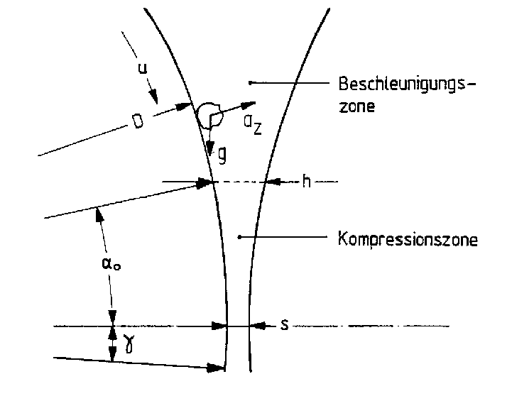
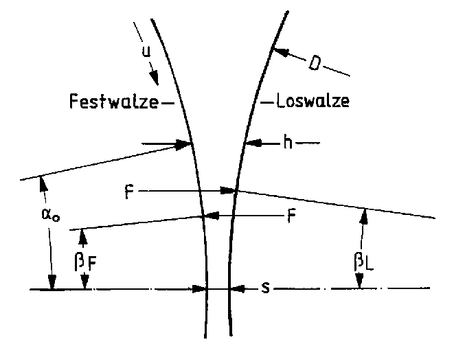
The material transport in the High Compression Roller Mills can be described with the help of throughput measurements and
by direct observation of the particle movement.
The throughput can be determined easily and is - in an adequately dimensioned mill - only marginally dependent on border
effects. In contrast the observation of the particle movement is limited to the edge zone which is only partially representative for the whole.
|
|
|
 |
|
|
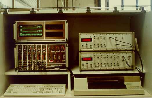
Measuring equipment of a lab-scale High
Compression Roller Mill / Institute for Mineral Processing of the TU Clausthal (Germany, 1989)
|
|
|
The pressure distribution in the compression zone is a characteristic for the stress of the material because by
determination of the maximum pressure the stress intensity can be identified and by integration the energy absorption can be calculated.
The throughput measurements with different roller patterns, recording of particle movements with a video system and the
installation of pressure sensors in the roller shell require a High Compression Roller Mill which constructively meets the following demands of the test method:
simple and quick change of the rollers
facility to install an inspection window for the observation of particle movements
facility to install a pressure sensor in the roller shell
Additionally the measuring technique must facilitate the registration of short-time pressure signals. An experimental
equipment with the necessary options was built by Lubjuhn, U. [25] within the work for his doctoral thesis. The construction of this especially designed lab-scale mill was advised by Dr. Dieter Schwechten during his time as a member of the scientific staff of the Institute for Mineral Processing at the Technical University Clausthal (Germany).
|
|
|
|
|
Comminution
grinding results for different materials
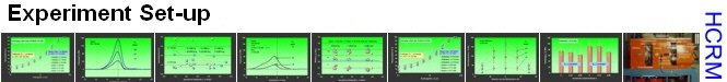
Exper. Setup
lab-scale mill, techn. data mill, intrumentation, feed materials, testing program, roller surface data, test execution
Throughput
literature, decoupling of throughput and comminution, energy absorption, characteristic
of different rollers, phenomenons, throughput results, elasticity, friction angle, specific throughput
Pressure Distribution
pressure diagrams
Press Tests
tests with a molding press
Modelling
mathematic model of the process
Signs and Symbols
nomenclature
|
|
|