|
|||
|
|
 |
|||||||
|
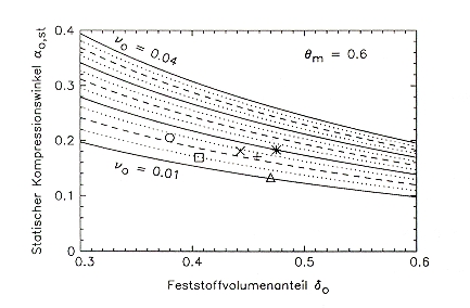
Set of characteristic curves for n0 and averaged (a0;n)-pairs from compression tests: quartz ^ 0.5/1.0 [] 1.0/2.0 o 4.0/6.0 mm limestone + 0.5/0.8 mm x 1.2/1.8 mm * 4.0/6.0 mm |
|||||||
|
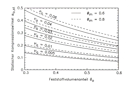
The compression tests delivered for each trial measured values for the compression angle a0 and the specific throughput n. Under the assumption that for the low roller speed of 0.3 m/s the measured compression angle is approximately equal to the static compression angle a0,st and the measured throughput corresponds to the throughput number n0 the validity of the model can be checked by using (a0;n)-pairs. For this reason for both parameters average values were calculated from the results of tests with the same material and similar adjustment of grinding force and circumferential speed and placed in the diagram above. For the three limestone fractions the resulting d0-values are between 44 and 48 % what matches well with the results of the bulk material investigations which delivered dSch-values of 47 to 48 %, see previous chapter. For the three quartz tests according the set of characteristic curves the following d0-values are resulting: Fraction 0.5/1.0 mm d0 = 47 %, fraction 1.0/2.0 mm d0 = 41 % and Fraction 4.0/6.0 mm d0 = 38 %. The buld material tests instead delivered for all three fractions a solid volume portion dSch of approx. 54 %. A conformance as for limestone can not be seen. A possible explanation for this deviation could be the fact that even at low circumferential speed slip appears for quartz fractions. As the equation above is only valid for slip-free material introduction at a = a0. Considering slip the slip-afflicted throughput number n*0 is n*0 = (a0,st2 / 2) (v0 / u) d0 [1 + d0 / qm (1 - d0)] (23) n*0 = (v0 / u) n0 (24) With this an estimation of the slip is possible, namely by calculating the slip-free throughput number n0 based on the measured values for the compression angle a0 and the solid volume portion of the bulk material dSch and by comparing it with the slip-affected throughput number n*0. The relation of n*0/n0 which is equal to the speed relation v0/u and therefore characterizes the slip has a value of 0.74 for the small quartz fraction, 0.55 for the medium fraction and 0.50 for the coarse fraction. A direct measurement of the slip by high speed camera video recording in the area of the compression zone was not possible because the glass of the observation window got scratches within seconds and was not transpararent any more. Nevertheless the relative speed between particles and roller could be determined in a angle range of a = 0.3 to 0.6.The over ten particles averaged values from the observation tests are shown in the attached spreadsheet. According to these values the particle speed of quartz is only 20 % of the circumferential speed of the smooth rollers compared to 35 % for limestone and smooth rollers and 60 % for rollers with profile. Because of the edge effects in the observation layer these results can only be used as an indication for the existance of slip in the entry layer of the compression zone. The influence of the maximum compaction qm on the location of n0-curves in the set of characteristic curves has a minor importance. The following diagram shows the small changes which occur at a higher compaction of qm = 0.8 instead of 0.6 (equal to dS = 0.9 instead of 0.8 and d0 = 0.5). |
|||||||
 |
|||||||
|
Set of characteristic curves for throughput number n0 at a maximum compaction of qm = 0.6 and 0.8. |
|||||||
|
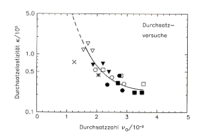
So, the previous discussion show that the throughput number can be calculated based on the solid volume portion and the static compression angle if the introduction of material in the entrance layer of the compression zone is slip-free. For soft or medium hard materials like limestone this precondition is obviously fulfilled, for the harder quartz and smooth rollers obviously not. Further on it seems to be possible with the help of such tests to receive first informations about the dimension of the slip in the entrance layer at a0. The throughput elasticity k characterizes the influence of speed on the throughput. During the throughput test it was observed that k was growing when n0 increased and that both parameters are obviously correlated. A correlation between k and n0 can be expected because of the following reasons: The throughput number n0 increases with the static compression angle a0,st which again is determined by the friction conditions. In the material bed situation the inner and outer friction is of relevance while in the direct contact situation only the outer friction is important. The acceleration of particles and therefore the impact of the centrifugal effect also depend on the friction. The centrifugal effect is more significant, means k is smaller, the stronger the particles are accelerated due to a better friction situation. There it can be expected that k and n0 have a controversial behaviour when the friction situation changes. Therefore it seems to reasonable to draw the measured values of k as a function of n0, see diagram below. It can be seen that all measured points are forming a group around the trend curve - with the exception of quartz with smooth rollers. The point is located far below the value extrapolated from the trend curve which means that the throughput is reacts less elastic on speed changes. This can be again a consequence of the significantly higher slip for this material pair, see the attached spreadsheet. |
|||||||
 |
|||||||
|
Throughput number n0 and throughput elasticity k for 1.) smooth rollers, all particle size fractions, x quartz * limestone and 2.) corrugated rollers, quartz v 0.25/1.0 o 1.6/6.3 [] 0.1/6.3 and limestone v 0.25/1.0 o 1.6/6.3 [] 0.1/6.3 |
|||||||
|
Therefore - under certain conditions - from the shown correlations the throughput number and throughput elasticity can be deducted. With known n0 and k then at a defined relative speed z = u/uc with uc = (g D / 2)0.5 the specific throughput n follows according to the formula 11 for n in the previous chapter phenomenons. For the determination of the roller dimensions D and L and the circumferential speed u for a given throughput more requirements have to be considered. For coarse feed material where a direct contact situation has to be expected the minimum roller diameter should be choosen in relation to the maximum particle size xmax or the characteristic particle size x80. From the perspective of a calm and stable operation it has to be claimed that (xmax/s) < 3 respectively (xmax/sD) < 3 should be fulfilled. Then an estimation can be done either with a s-value based on experience (0.5 % to 2.0 % for smooth rollers, 1.5 to 3.5 % for rollers with profile) or with a calculated s-value according forumla 7 in the previous chapter phenomenons. Starting with equation 1 (see chapter throughput characteristic) Mt = dSrsLvS it follows for the length-diameter relation: L / D = (1 / u D2) (Mt / r) (u / v0) {qm (1 - d0) / d0 (1 - cos a0) [d0 + qm (1 - d0)]} (25) After pre-definition respectivley knowledge of Mt , d0 , qm , r and a0 the ratio (L/D) is only dependent on the roller diameter and the circumferential speed. The slip in the entrance layer of the compression zone remains an open question but according to the obtained results it can be neglected for soft to medium hard materials. For the circumferential speed an upper limit exists due to the dynamic load of the bearings, generally industrial mills are running at speeds between 0.8 and 1.8 m/s. When the speed is defined by design then with the previously discussed minimal diameter Dmin follows an upper (L/D)-value. But also the (L/D)-ratio is limited due to shaft and bearing loads and other design restrictions. The industrial mills so far have an (L/D)-ratio between 0.3 and 1.0. Should the calculated value according equation 25 be too big then a roller diameter bigger than the minimal roller diameter has to be chosen. |
|||||||
|
|
|